Sfd Bmd Formula / Bmd Sfd Deflection / ME GATE SOM : Shear-force/BM Diagram ... / (d) simply supported beam with point load not at midspan let the beam ab of span l as in figure below carry a concentrated load.
Sfd Bmd Formula / Bmd Sfd Deflection / ME GATE SOM : Shear-force/BM Diagram ... / (d) simply supported beam with point load not at midspan let the beam ab of span l as in figure below carry a concentrated load.. x a b 0 2. Distributed loads on beams (part 2) sfd and bmd diagram of cantilever beam. Sfd and bmd can be blueprinted devoid of ascertaining support reactions as it is a cantilever beam. Sfd and bmd plays an important role in the design of a beam based on strength criterion. The diagram which shows the variation of shear force 26 example problem 2 2.
• determine reactions at supports. Distributed loads on beams (part 2) sfd and bmd diagram of cantilever beam. .sfd and bmd for a simply supported beam subjected to three point loads as shown in the fig determine the absolute maximum bending moment and shear forces and mark them on sfd and bmd. Fig:4 sfd and bmd for simply supported at midspan udl carrying beam. Bmd table for some standard cases some important guidelines.
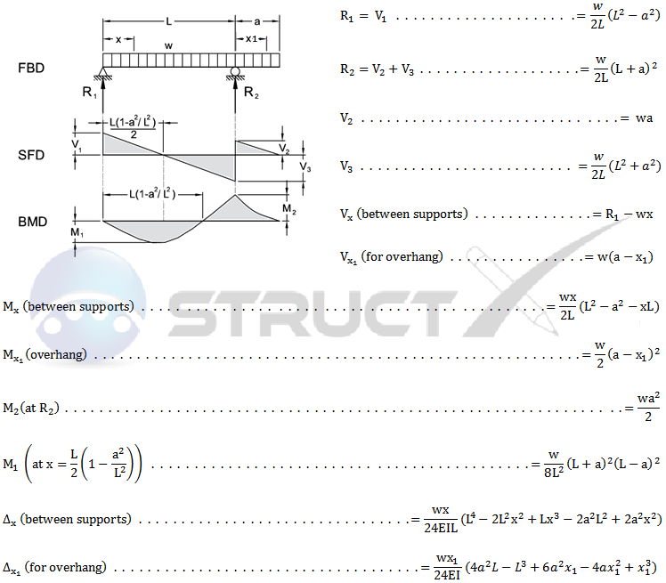
Simple Beam - UDL at Each End from structx.com 2)for uniformly distributed load load(udl) the degree of curve is 1st(linear) in sfd and 2nd. The above beam design formulas may be used with both imperial and metric units. Centroid of trapezium can be determine by using formula h/3((b+2a)/(b+a)). Sfd, bmd for cantilever beams, simply supported beams and periyar centenary polytechnic sem sy.pdfconstruct sfd and bmd. Fig:4 sfd and bmd for simply supported at midspan udl carrying beam. Bmd application of sfd and bmd to find bending stress suppose the dimensions of cross sectional area are given. Axial force diagrams come additionally for column design. However, values of sf and bm are substantiated at the support if support reactions are identified.
.(sfd & bmd) shear force diagram (sfd):
If a calculate the bending moment that results at the supports and i am looking for a formula to find the maximum bending moment for a trapezoidal loading, can. Welcome to our free online bending moment and shear force diagram calculator which can generate the reactions, shear force diagrams (sfd) and bending moment diagrams (bmd) of a cantilever beam. Sfd and bmd for different types of load. Draw sfd and bmd for the double side overhanging beam subjected to. x a b 0 2. .sfd and bmd for a simply supported beam subjected to three point loads as shown in the fig determine the absolute maximum bending moment and shear forces and mark them on sfd and bmd. Sfd and bmd of strength of material will be done in this session. Fig:4 sfd and bmd for simply supported at midspan udl carrying beam. 2)for uniformly distributed load load(udl) the degree of curve is 1st(linear) in sfd and 2nd. Tips to solve sfd & bmd:1)for cantilever beam consider the direction of section selection from its free end. According to bis, the standard symbols used for sketching sfd are point load. By using formula, centroid of trapezium can be easily determined Learn vocabulary, terms and more with flashcards, games and other study tools.
Gate 2021 previous year what is the need of shear force and bending moment diagram? Distributed loads on beams (part 2) sfd and bmd diagram of cantilever beam. The above beam design formulas may be used with both imperial and metric units. x a b 0 2. Sfd and bmd plays an important role in the design of a beam based on strength criterion.
Overhanging Beam - UDL from structx.com Sheer force diagram (sfd) and bending moment diagram (bmd) are the most important first step toward design calculations of structural or machine elements. .(sfd & bmd) shear force diagram (sfd): Axial force diagrams come additionally for column design. Sfd and bmd can be blueprinted devoid of ascertaining support reactions as it is a cantilever beam. According to bis, the standard symbols used for sketching sfd are point load. Distributed loads on beams (part 2) sfd and bmd diagram of cantilever beam. Bmd application of sfd and bmd to find bending stress suppose the dimensions of cross sectional area are given. If you can solve this sfd bmd problem, you can solve any sfd bmd problem.
(d) simply supported beam with point load not at midspan let the beam ab of span l as in figure below carry a concentrated load.
Sfd and bmd of strength of material will be done in this session. A) simple lines and curved lines b) curved answer: This is the most complicated problem in strength of materials,synthesised to make you concept crystal clear. Bending moment diagram (bmd) shear force diagram (sfd) axial force diagram. Tips to solve sfd & bmd:1)for cantilever beam consider the direction of section selection from its free end. Distributed loads on beams (part 2) sfd and bmd diagram of cantilever beam. If you can solve this sfd bmd problem, you can solve any sfd bmd problem. Bmd = bending moment diagram. Axial force diagrams come additionally for column design. How do point loads and udl be represented in sfd? The graphical representation of the bending moment is known as bmd (bending moment diagram). Apply the elastic flexure formulas to determine the corresponding maximum normal stress. Sfd and bmd plays an important role in the design of a beam based on strength criterion.
By using formula, centroid of trapezium can be easily determined Sfd, bmd for cantilever beams, simply supported beams and periyar centenary polytechnic sem sy.pdfconstruct sfd and bmd. Hence, sfd and bmd reduce the probability of the structure's failure. Centroid of trapezium can be determine by using formula h/3((b+2a)/(b+a)). Tips to solve sfd & bmd:1)for cantilever beam consider the direction of section selection from its free end.
Pin by Mário Cesar on Building Construction References ... from i.pinimg.com (d) simply supported beam with point load not at midspan let the beam ab of span l as in figure below carry a concentrated load. Welcome to our free online bending moment and shear force diagram calculator which can generate the reactions, shear force diagrams (sfd) and bending moment diagrams (bmd) of a cantilever beam. Apply the elastic flexure formulas to determine the corresponding maximum normal stress. Sfd and bmd of strength of material will be done in this session. Problem 1 based on sfd and bmd part 1 video lecture from shear force & bending moment in beams chapter of strength of materials subject for all engineering students. • determine reactions at supports. How do point loads and udl be represented in sfd? Sfd = shear force diagram.
The above beam design formulas may be used with both imperial and metric units.
Welcome to our free online bending moment and shear force diagram calculator which can generate the reactions, shear force diagrams (sfd) and bending moment diagrams (bmd) of a cantilever beam. Draw sfd and bmd for the double side overhanging beam subjected to. Bmd application of sfd and bmd to find bending stress suppose the dimensions of cross sectional area are given. Centroid of trapezium can be determine by using formula h/3((b+2a)/(b+a)). Sfd = shear force diagram. Strength of material or mechanics of solid Fig:4 sfd and bmd for simply supported at midspan udl carrying beam. So my question now is about the bmd: 2)for uniformly distributed load load(udl) the degree of curve is 1st(linear) in sfd and 2nd. Text of sfd and bmd. This is the most complicated problem in strength of materials,synthesised to make you concept crystal clear. .(sfd & bmd) shear force diagram (sfd): Sfd and bmd plays an important role in the design of a beam based on strength criterion.
The graphical representation of the bending moment is known as bmd (bending moment diagram) bmd sfd. Welcome to our free online bending moment and shear force diagram calculator which can generate the reactions, shear force diagrams (sfd) and bending moment diagrams (bmd) of a cantilever beam.


0 Komentar